Skip to content
Product Details
Overview
NP-RID-Sender is a broadcast-mode UAV remote identification transmitter from NextPilot, compliant with the GB 46750-2025 standard. It broadcasts UAV operating status signals over WiFi or Bluetooth to meet UAV flight supervision requirements. It currently supports MAVLink and DroneCAN connections and works with autopilots such as ArduPilot and PX4 — if you need support for other autopilots or protocols, custom development is available.
Features
- Communicates with the autopilot to obtain UAV operating status;
- WiFi beacon frame broadcast;
- Bluetooth 5 broadcast;
- View UAV status through a web page;
- WiFi telemetry function;
- Virtual RID simulation function;
- Parameter configuration — connect to the device with a serial debug assistant and quickly set all parameters through parameter commands!
- OTA upgrade support;
Specifications
- Supported main control chips: ESP32-S3 / ESP32-C3;
- Interfaces: 2 serial ports (autopilot serial port and debug serial port), 1 USB, 1 CAN;
- Supported input protocols: MAVLink, DroneCAN;
- Supported transmit signal types: WiFi broadcast beacon frames, Bluetooth 5;
- Transmit power: 20 dBm;
- Transmit protocol: GB46750;
Hardware Variants
The following hardware versions are currently supported:
- NP-RID-Sender-S3-GH
- NP-RID-Sender-C3-PinMini
| Hardware Appearance | Hardware Name | Description |
|---|---|---|
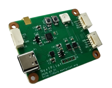
| NP-RID-Sender-S3-GH | Main control chip: ESP32-S3 All features available, can be mounted directly on the UAV External antenna supported Debug serial port is UART2 |
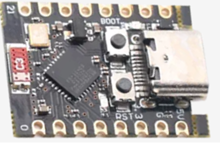 | NP-RID-Sender-C3-PinMini | Main control chip: ESP32-C3 No external antenna; Bluetooth only, no WiFi broadcast; generally used for testing Debug serial port is UART0 |
Specifications Table
NP-RID-Sender-S3-GH
The external interfaces of each hardware variant are described below:
| Interface | Pin Assignment | Remarks |
|---|---|---|
| USB | USB, Type-C | After plugging into a computer, two USB devices appear: the first is JTAG (program download and debug), the second is USB-to-serial (UART0), which requires a serial driver |
| UART1 | RX: GPIO17 TX: GPIO18 | Autopilot serial port Default baud rate 115200 Connector J6 |
| UART2 | RX: GPIO44 TX: GPIO43 | Debug serial port Used for debugging and parameter configuration, accessed through the second USB serial port Default baud rate 115200 Connector J4 |
| CAN | RX: GPIO38 TX: GPIO47 | Connect directly to the autopilot CAN bus |
NP-RID-Sender-C3-PinMini
The external interfaces of each hardware variant are described below:
| Interface | Pin Assignment | Remarks |
|---|---|---|
| USB | USB, Type-C | Program download and debug, JTAG |
| UART0 | RX: GPIO20 TX: GPIO21 | Debug serial port Used for debugging and parameter configuration Default baud rate 115200 |
| UART1 | RX: GPIO2 TX: GPIO3 | Autopilot serial port Default baud rate 115200 |
| CAN | RX: GPIO4 TX: GPIO5 | Requires an external CAN transceiver |
Downloads
| Board | Current Firmware Version | Click to Download |
|---|---|---|
| NP-RID-Sender-S3-GH | V1.1 | OTA app firmware |
| NP-RID-Sender-C3-PinMini | V1.0 | OTA app firmware |